AccuMASTER Parking Sensor SST (Digital Download)
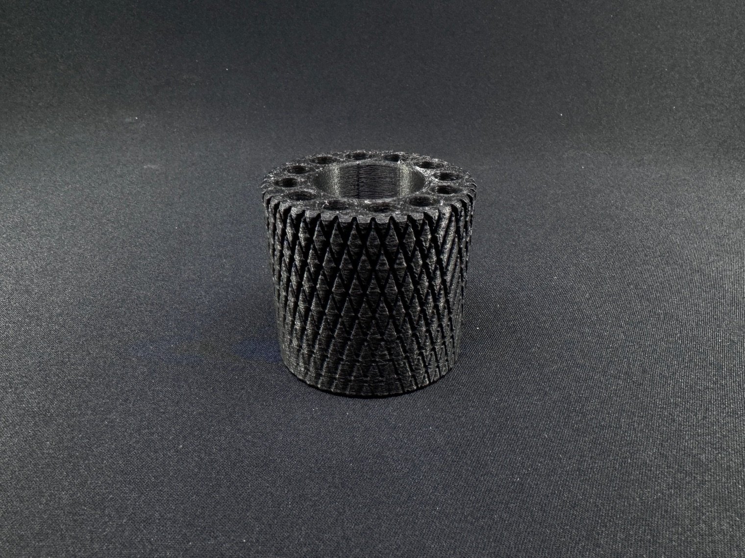
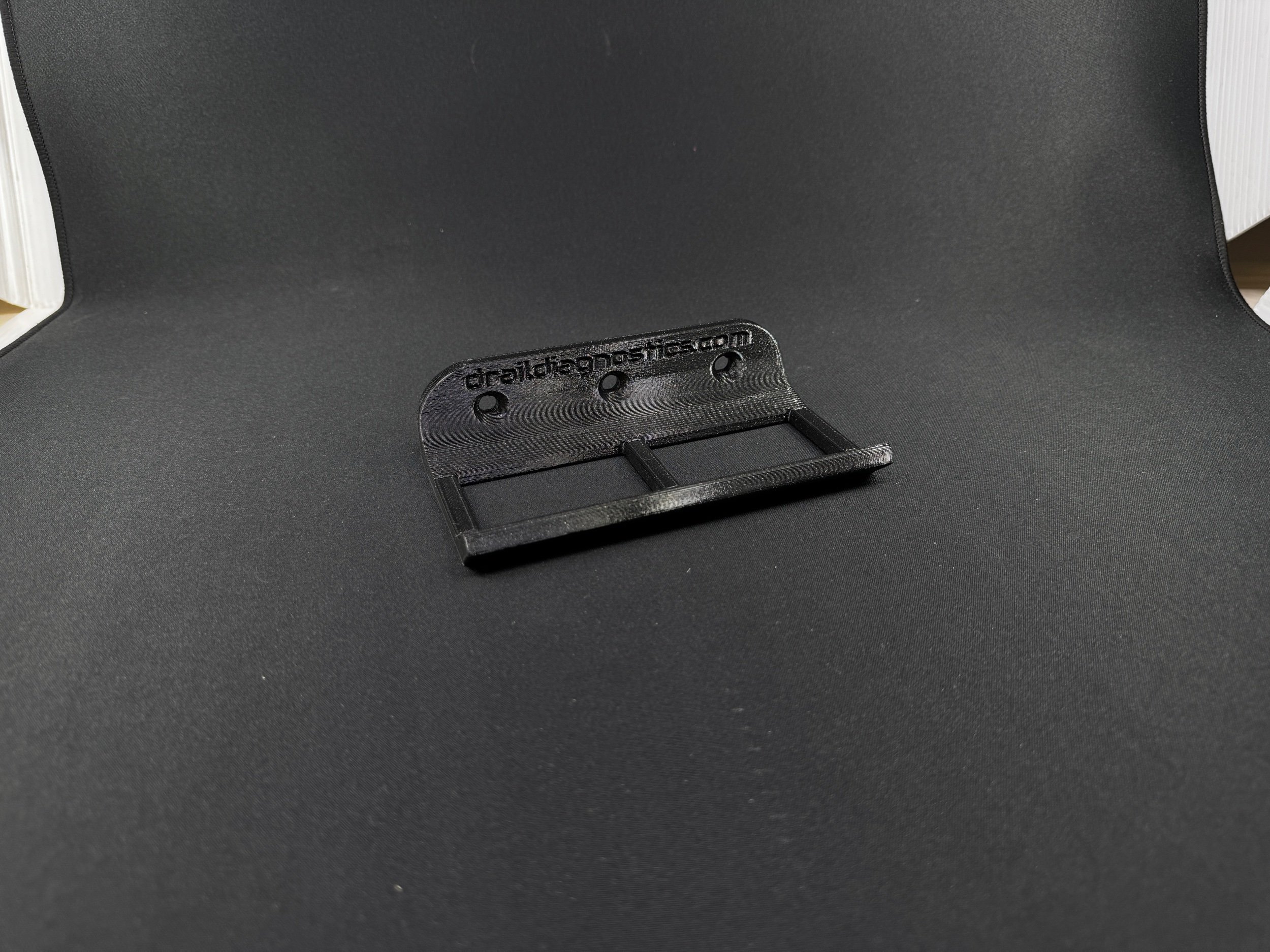
During bumper registration on many Toyota/Lexus vehicles, measuring the angle of the parking sensor in relation to 90 degrees can be a pain with just the angle finder or if you don’t have the SST attachment from Toyota (which I believe only fits one brand). The bracket is 2 pieces, the bracket portion and the small round extension.
————————————————————————————
This is for the digital download ONLY to 3D print yourself. See additional info for needed parts and info before purchasing! Some downloads will include a little magnet jig for easy repeatability of installing the magnets. Just make sure you get the polarity right!
Parts needed to complete project:
Threaded brass insert for plastics:
I modeled the hole to except a brass insert with the max diameter of 6.3mm and 8.1mm total length (you can use a shorter in length insert if you want)
2 small round magnets
You can get these off amazon, they just need to be 3mm thick and 6mm in diameter (they are press fit but you are more than welcome to add a drop of glue - just MAKE SURE if you use glue that it does squish up and allow the bracket not to sit flat onto the angle gauge.
1 Hexcap Bolt
You need one hex cap bolt to fit whatever brass insert you choose. No more than 12mm in length of the bolt portion, no more than 7.5mm head diameter (12mm is measured from the bottom of the hex cap / head of the bolt - not full length).
Print settings:
I use a .06 nozzle, but you can use a standard .04 nozzle if you would like. With the .06, standard 2 walls is good enough for this, with a .04 nozzle you can either do 2 walls or 3 walls. It’s really not super important for this particular print IMO.
If you are using the .3MF file the print orientation will already be set up for correct orientation. If you are using the .STL file you will need to make sure you print the bracket portion with the “Parking Sensor Angle SST” letterings facing the print bed. The little extension you will need to print obviously face down on either side.
As far as assembling, on the small extension piece make sure you put the heat insert on the side that WASN’T printed facedown on the print bed. This insures that the flat portion will touch the parking sensor.
Always keep in mind this is not an official SST from Toyota. This print works for me and I have tested this vs the actual SST from Toyota and results are similar. I hold no responsibly of inaccurate measurements due to poor printing on the user end or assembly.


